Introduction to Arduino
Introduction to Arduino circuits and breadboarding
What is Arduino?
●
Arduino is an open-source
electronics prototyping platform built on user-friendly hardware and software.
[Source:
https://docs.arduino.cc/learn/starting-guide/getting-started-arduino]
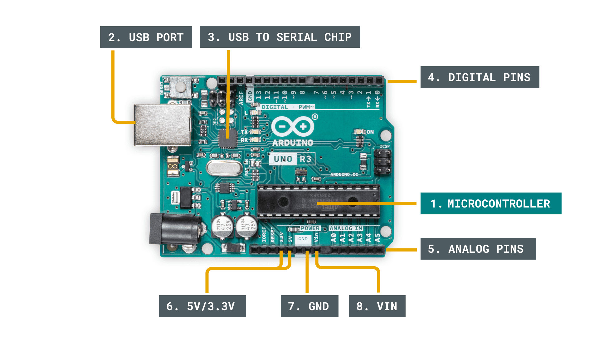
1. Microcontroller - this is the brain of an Arduino, and is the
component that we load programs into. Think of it as a tiny computer, designed
to execute only a specific number of things.
2.
USB port - used to connect
your Arduino board to a computer.
3. USB to Serial chip - the USB to Serial is an important component,
as it helps translating data that comes from e.g. a computer to the on-board
microcontroller. This is what makes it possible to program the Arduino board
from your computer.
4. Digital pins - pins that use digital logic (0,1 or LOW/HIGH).
Commonly used for switches and to turn on/off an LED.
5. Analog pins - pins that can read analog values in a 10 bit
resolution (0-1023).
6. 5V / 3.3V pins- these pins are used to power external components.
7. GND - also known as ground,
negative or simply -, is used to complete a
circuit, where the electrical level is at 0 volt.
8. VIN - stands for Voltage In, where you can connect external power
supplies.
Basics
of Circuits :
●
In order for electricity to flow
through a circuit, there must be at least one active electronic component and a
conductive medium, such wires.
●
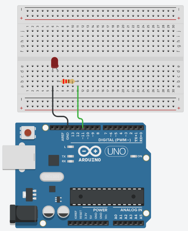
An LED circuit is an elementary
example of a circuit.
●
A cable is connected to an Arduino
pin, then to an LED through a resistor to shield it from excessive current, and
lastly to the ground pin (GND).
●
The microprocessor on the Arduino
board allows an electric current to travel through the circuit when the pin is
set to a HIGH state, turning on the LED.
●
An LED circuit is an
elementary example of a circuit.
●
A cable is connected to
an Arduino pin, then to an LED through a resistor to shield it from excessive
current, and lastly to the ground pin (GND).
●
The microprocessor on
the Arduino board allows an electric current to travel through the circuit when
the pin is set to a HIGH state, turning on the LED.
●
Since there is no longer
any electric current flowing through the circuit, the LED will turn off when
the pin is set to a LOW state.


Comments
Post a Comment